4.2. Operation
After finishing the tension calibration and the measured tension is right, the controller can be tested with manual operation and automatic operation. First use manual operation, if the tension system works well(get the stable tension), the controller can be switched into automatic mode to perform closed-loop tension control.
4.2.1. Manual operation
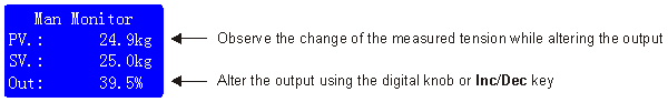
In manual mode, the indicator MAN will be lit, the output can be altered using the Inc/Dec key or turning the digital knob, the output is limited by Max Output[20].
The measured tension will be changed during the altering of the output, after the measured tension of the web is stable, the controller is ready to be switched to the automatic operation mode.
To switch to automatic mode, just press the AUTO/MAN key. While switching the controller from manual mode to automatic mode, the measured tension before switching will be used as the setting tension for automatic control, this makes the smooth transition.
4.2.2. Automatic operation
In automatic mode, the indicator AUTO will be lit, the setting tension can be altered using the digital knob or the Inc/Dec keys. The adjustable range is limited by the Max Setvalue[18] and Min Setvalue[19].
The setting tension refers to the process of control, the value expected to reach the goal of tension. In automatic mode, the controller compares the measured tension with the desired tension, called the 'setting tension', and regulates the output power to make them the same.
The measured tension is referred to as the Process Value, or 'PV' for short while the setting tension is referred to as the Setting Value, or 'SV' for short.
If the tension measurement fails, the error message will appear and the controller will be automatically switched into the manual mode, the automatic/manual mode can not be switched at this time.
Note that in stopping mode, the AUTO LED flashes.
To switch to manual mode, just press the AUTO/MAN key.

4.2.3. Setting of PI
In automatic mode, the stability and control precision of the tension system is affected by proportional band, integral time and dead band, if the system is not stable, alter the value of the Prop. Band[05], Inte. Time[06] and Dead Band[07] properly.
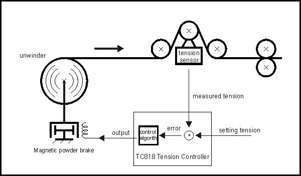
The controller compares the measured tension with the setting tension, and regulates the output power with the PI algorithm to make them the same.
Therefore, appropriate setting of the proportion band, integral time and dead band is very important.
4.2.3.1. Proportional band
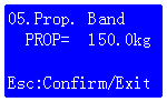
The controller alters the output using the proportion of the error between the setting tension and the measured tension, value range: 0.1-999.9.
The smaller proportional band, the faster response but oscillation and un-stability.
The greater proportional band, the slower response and more stable.
Generally, set the value to 2-3 times measurement range.
4.2.3.2. Integral time
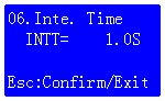
The integral time is used to cancel the static error, value range: 0.1-10.0 seconds.
The smaller integral time, the faster response but oscillation and un-stability.
The greater integral time, the slower response and more stable.
Generally, set Inte. Time[06] to 1.0 seconds.
4.2.3.3. Dead band

The greater dead band, the more stable, but slow response.
Generally, set Dead Band[07] as 0.5 to 1.0 times setting tension.
4.2.4. Run and Stop
4.2.4.1. Run/Stop switch

The start and stop operation is controlled by the Start/Stop Switch(S1) connected to MC1 and MCC.
If the Sync. Mode[39] function is enabled, the start and stop of the tension system is not only controlled by the Start/Stop Switch but also be controlled by the running speed of the tension sensing roller. To use the Sync start/stop function, a proximity switch or encoder must be mounted on the tension sensing roller to monitor the running revolution.(i.e. the running frequency)
When S1 is ON,if the running frequency of the tension sensing roller is great than Start Freq.[03], system starts, the AUTO LED will be lit.
When S1 is ON, if the running frequency of the tension sensing roller is less than Start Freq[03], system stops, the AUTO LED will flash.
In automatic tension control systems, normally short-circuit the MC1 and MCC, the controller will start or stop the system automatically according to the running frequency of the tension sensing roller.
4.2.4.2. Start process
Once switch S1 on, the controller will start the automatic control to the tension system, the controller performs the closed-loop control, LED AUTO will be it.
4.2.4.3. Stop process
When the system is running, once turn the switch S1 off, the output before stopping(turn MC1 off) times Stop Gain[10] G will be applied to the running reel to brake the reel, at the same time, the stop timer starts count, the controller perform automatic control during stop process, when Stop Time[11] times up, the controller enters the opened-loop control and output the start output with value of P.on to generate prepared tension. In stopping mode, indicator AUTO flashes.
4.2.4.4. Start output selection
The start output of the controller is selected using the Start output selector S4.
When S4 is on, the output before stopping(turn MC1 off) will be used as start output.
When S4 is off, the presetting Start Output[08] will be used as start output.
Generally use start output selector as follow:
1. When system holding, keep S4 on, with the output memory function, the controller will restart with the output before stopping.
2. When replacing new material reel, keep S4 off, the controller will start with the pre-setted Start Output[08].
4.2.5. Reel exchange
In the two-reel operation tension systems, the reel exchange is controlled by the Reel exchange switch. This function is applicable when material on reel is over or full.

4.2.5.1. Reel exchange switch
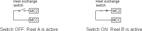
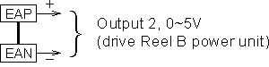
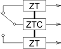
The reel exchange function is controlled by the switch which is connected to terminal MC2 and MCC. When the switch is OFF, Reel-A will be active while the switch is ON, Reel-B will be active. See the figure above.
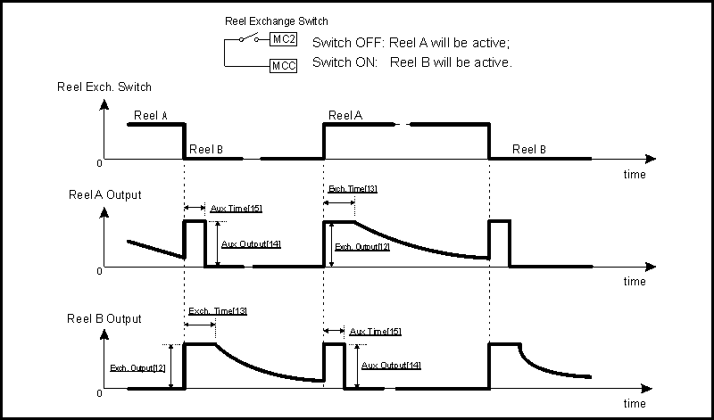
4.2.5.2. Exchange of unwinder
We assume that Reel-A is connected to OUT1 and Reel-B is connected to OUT2.
In unwinding systems(Wind Mode[37]=Unwind), suppose that Reel-A is active, at this time, turns the Reel exchange switch from OFF to ON, the control output exchanges to Reel-B, the output value is the pre-setted Exch. Output[12], when the Exch. Time[13] times up, the automatic closed-loop control starts.
At the same time, the Aux Output[14] is applied to Reel-A lasts for Aux Time[15] to brake Reel-A.
For switching reel B to reel A, just reverse the above process. The figure in the next page illustrates the process clearly.
4.2.5.3. Exchange of winder
In winding systems(Wind Mode[37]=Wind), suppose that Reel-A is active, at this time, turns the Reel exchange switch from OFF to ON, the Aux Output[14] will be applied to Reel-B, this make Reel-B starts running, when the timer Aux Time[15] times up, the control output will be switched to Reel-B, the output value is the pre-setted Exch. Output[12], when the Exch. Time[13] times up, the automatic closed-loop control starts.
For switching Reel-B to Reel-A, just reverse the above process. See the figure in the next page.

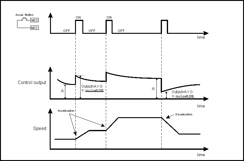
4.2.6. Acceleration/Deceleration
The acceleration and deceleration operation is controlled by the Accel. button which is connect between MC3 and MCC.
Once the Accel. button is pressed, the output before the button is pressed times Inc Coeff.[16] will be the control output, this makes the system speed accelerates or decelerates.
In unwinding systems, if Inc Coeff.[16] < 1.00, speed accelerates; If Inc Coeff.[16] > 1.00, speed decelerates. In winding systems, if Inc Coeff.[16] < 1.00, speed decelerates; If Inc Coeff.[16] > 1.00, speed accelerates.
Note that the acceleration and deceleration operation does not works in the reel exchange, system holding and starting states.
4.2.7. Tension alarm
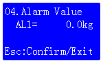
When the measured tension is less than the setting Alarm Value[04],the tension alarm relay will be 'ON', at the same time, the indicator ALM will be lit.
4.2.8. Action mode
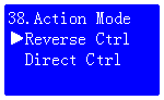
This parameter control the feedback mode of the tension system:
Normal mode: When the measured tension > setting tension, the output decreases, this is also called negative feedback;
Feed mode: When the measured tension > setting tension, the output increases, this is also called positive feedback.